UE 5G NR Search Space


UE 5G NR Search Space:
     In this article, we will describe search space types viz. Type0, Type0A, Type1, Type2, Type3, and UE specific search space sets as defined in 5G NR standards. It mentions fields used in the Search Space information element (IE) used by the RRC layer.
Introduction:
=>It is similar to the LTE search space.
=>It is the area in the downlink frame where PDCCH might be transmitted.
=>This area has been monitored by the UE to search for the PDCCH carrying data (i.e. DCI).
=>There are two types of search spaces viz. common and UE-specific. These are mentioned in the following table.

5G NR Search Space Types
Description
Type0
PDCCH common search space set configured by searchSpaceZero in MasterInformationBlock or by searchSpaceSIB1 in PDCCH-ConfigCommon for a DCI format with CRC scrambled by a SI-RNTI on a primary cell
Type0A
PDCCH common search space set configured by searchSpace-OSI in PDCCH-ConfigCommon for a DCI format with CRC scrambled by a SI-RNTI on a primary cell
Type1
PDCCH common search space set configured by ra-SearchSpace in PDCCH-ConfigCommon for a DCI format with CRC scrambled by a RA-RNTI, or a TC-RNTI on a primary cell
Type2
PDCCH common search space set configured by pagingSearchSpace in PDCCH-ConfigCommon for a DCI format with CRC scrambled by a P-RNTI on a primary cell
Type3
PDCCH common search space set configured by SearchSpace in PDCCH-Config with searchSpaceType = common for DCI formats with CRC scrambled by INT-RNTI, or SFI-RNTI, or TPC-PUSCH-RNTI, or TPC-PUCCH-RNTI, or TPC-SRS-RNTI and, only for the primary cell, C-RNTI, or CS-RNTI(s)
UE specific search space
This set configured by SearchSpace in PDCCH-Config with searchSpaceType = ue-Specific for DCI formats with CRC scrambled by C-RNTI, or CS-RNTI(s).

Search Space Information Element (IE)
Following structure mentions various fields used by RRC Search Space Information Element (IE).
=> This IE defines how and where to search for PDCCH candidates.
=> Each search space is associated with one ControlResourceSet.

RRC parameters:

searchSpaceId: Identity of the search space. SearchSpaceId = 0 identifies the SearchSpace configured via PBCH (MIB) or ServingCellConfigCommon. The searchSpaceId is unique among the BWPs of a Serving Cell

controlResourceSetId : The CORESET applicable for this SearchSpace.
    Value 0 identifies the common CORESET configured in MIB and in ServingCellConfigCommon
    Values 1..maxNrofControlResourceSets-1 identify CORESETs configured by dedicated signalling  

monitoringSlotPeriodicityAndOffset: Slots for PDCCH Monitoring configured as periodicity and offset. Corresponds to L1 parameters 'Monitoring-periodicity-PDCCH-slot' and 'Monitoring-offset-PDCCH-slot'. For example, if the value is sl1, it means that UE should monitor the SearchSpace at every slot. if the value is sl4, it means that UE should monitor the SearchSpace in every fourth slot.

monitoringSymbolsWithinSlot : Symbols for PDCCH monitoring in the slots configured for PDCCH monitoring (see monitoringSlotPeriodicityAndOffset).The most significant (left) bit represents the first OFDM in a slot. The least significant (right) bit represents the last symbol. Corresponds to the L1 parameter 'Monitoring-symbols-PDCCH-within-slot'. This indicates the starting OFDM symbols that UE should search for a search space. For example, if the value is '1000000000000', it means that UE should start searching from the first OFDM symbol. if the value is '0100000000000', it means that UE should start searching from the second OFDM symbol.

nrofCandidates: Number of PDCCH candidates per aggregation level. Corresponds to L1 parameter 'Aggregation-level-1' to 'Aggregation-level-8'. The number of candidates and aggregation levels configured here applies to all formats unless a particular value is specified or a format-specific value is provided (see inside search space type)

search space type : Indicates whether this is a common search space (present) or a UE specific search space as well as DCI formats to monitor for

common: Configures this search space as common search space (CSS) and DCI formats to monitor.

dci-Format0-0-AndFormat1-0: If configured, the UE monitors the DCI formats 0_0 and 1_0 with CRC scrambled by C-RNTI, CS-RNTI (if configured), SP-CSI-RNTI (if configured), RA-RNTI, TC-RNTI, P-RNTI, SI-RNTI

dci-Format2-0: If configured, UE monitors the DCI format format 2_0 with CRC scrambled by SFI-RNTI

nrofCandidates-SFI : The number of PDCCH candidates specifically for format 2-0 for the configured aggregation level. If an aggregation level is absent, the UE does not search for any candidates with that aggregation level. Corresponds to L1 parameters 'SFI-Num-PDCCH-cand' and 'SFI-Aggregation-Level'

dci-Format2-1 : If configured, UE monitors the DCI format format 2_1 with CRC scrambled by INT-RNTI

dci-Format2-2 : If configured, UE monitors the DCI format 2_2 with CRC scrambled by TPC-PUSCH-RNTI or TPC-PUCCH-RNTI

dci-Format2-3 : If configured, UE monitors the DCI format 2_3 with CRC scrambled by TPC-SRS-RNTI

ue-Specific : Configures this search space as UE specific search space (USS). The UE monitors the DCI format with CRC scrambled by C-RNTI, CS-RNTI (if configured), TC-RNTI (if a certain condition is met), and SP-CSI-RNTI (if configured)


5G NR CORESET

5G NR CORESET:

            CORESET is a common resource set that is set of multiple physical resources (Specific in NR downlink resource grid) and set of parameters that are used to carry PDCCH/DCI information. The PDDCH/DCI information will be the same as LTE.                               Unlike LTE there is no PCFICH in 5G as PCFICH gives information about PDCCH OFDM symbol in the time domain and in the frequency domain, there is no need to specify as it spreads across the whole channel bandwidth.

       But in 5G, the frequency region should be specific, and It can be signaled by the RRC signaling message.    


LTE
5G(NR)
Time Domain resources
PCFICH indicator(No of OFDM symbol) CFI.
MaxCORSETDuration in RRC signaling message (Max 3).
Frequency domain resources
there is no need to specify as it spreads across whole channel bandwidth.
Frequencies domain resources messages are signaled by RRC, and each bit corresponds to a group of 6RBs.


       The network can define a common control region and UE specific control region. The number of CORESET is limited to 3 per BWP (Bandwidth part) including both common and UE specific CORESET.

=> Frequency allocation in CORESET configuration can be contiguous or non-contiguous.

=> In the time domain, CORESET configuration spans 1 to 3 consecutive OFDM symbols.

=> REs in CORESET are organized in REGs (RE Groups).

=> Each REG consists of 12 REs of one OFDM symbol in one RB.


Parameters of CORESET are as follows.
TerminologyDescription
RE (Resource Element)The smallest unit of resource grid, 1 subcarrier x 1 OFDM symbol
REG (Resource Element Group)Made of 1 RB (Resource Block) i.e. 12 REs x 1 OFDM symbol
REG Bundles1 REG bundle is made of multiple REGs, Bundle size is specified by parameter "L".
CCE (Control Channel Element)One CCE is made of multiple REGs.
Aggregation levelIt indicates the number of allocated CCEs for PDCCH. It can be 1/2/4/8/16.

The Time-domain and frequency-domain parameters of CORESET are defined in TS 38.211 document. RRC signaling message consists of the following fields.
=>  NRBCORESET: The number of RBs in the frequency domain in CORESET.
=>  NSymbCORESET: The number of symbols in the time domain in CORESET. This can be               1/2/3.
=>  NREGCORESET: The number of REGs in CORESET.
=>  L: REG bundle size

RRC parameter structure of CORESET:


1- ControlResourceID: Bit 0 identifies common coreset and bit 1 identifies coreset for dedicated signaling. This ID should be unique for all BWP.

2- FrequencyDomainResources: Each bit corresponds to the group of 6RBs in the frequency domain.

3- maxCORESETDuartion: Contiguous time duration of the CORESET in OFDM symbols.

4- CCE-REG-MappingType: Mapping Method of CCE to REG. CCE aggregation level could be 1,2.4,8 and 18.


Use of CORESET in NR PDCCH channel

         A PDCCH channel is confined to one CORESET and transmitted with its own DMRS (Demodulation Reference Signal). Hence UE specific beam-forming of the control channel is possible.
=> PDCCH channel is carried by 1/2/4/8/16 CCEs (Control Channel Elements) to carry various DCI payload sizes or coding rates.
=> Each CCE consists of 6 REGs.
=> The CCE to REG mapping for CORESET can be interleaved (to support frequency diversity) or non-interleaved (for localized beam-forming).


5G(NR): Frame structure( Slots and symbols Formats)


5G(NR): Numerologies and Frame structure( Slots and symbols Formats)


               In this post, we will discuss about NR numerologies and frame structure. Numerology (3GPP term) is defined by Sub Carrier Spacing (SCS) and Cyclic Prefix (CP).

   In LTE, there is no need for any specific term to indicate the subcarrier spacing because there is only one subcarrier spacing, which is 15KHz, but there are several different types of 
subcarrier spacing in NR.
Slot Structure:
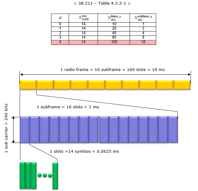
       The transmission of Downlink and Uplink are organized into frames. Each frame is of 10-millisecond duration. Each frame is divided into 10 subframes of 1 millisecond, and the subframe is further divided into slots according to numerology.
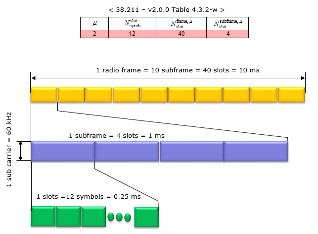
In LTE, only 2 slots are available. But in NR, the number of slots varies according to the numerology. in 1 slot, the number of symbols are fixed that is 14-with normal cyclic prefix(CP) and 12-with extended CP. 
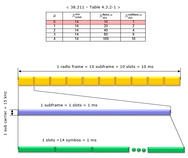
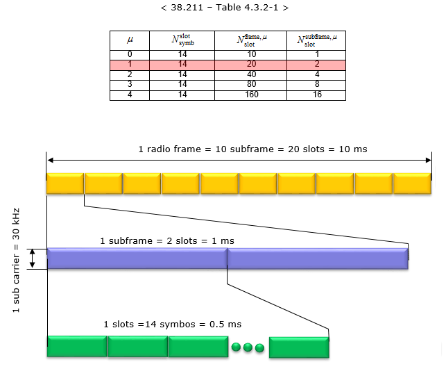
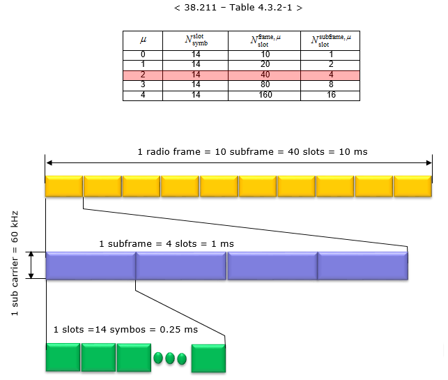
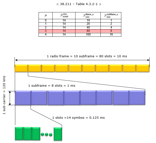
The following table summaries number of slots in a sub-frame/frame for each numerology with normal prefix.

Normal CP
Numerology = 0

Numerology 0 means 15 kHz subcarrier spacing. in this a sub-frame has only one slot available in it, it means that a radio frame contains 10 slots in it. The number of OFDM symbols are 14 within each slot.


 Numerology = 1

Numerology 1 means 30 kHz subcarrier spacing. in this configuration, a subframe is divided into 2 slots, it means a radio frame contains total of 20 slots in it. The number of OFDM symbols within a slot are 14 symbols.


Numerology = 2

Numerology 2 means 60 kHz subcarrier spacing. In this configuration, a subframe is divided into 4 slots, it means a radio frame contains total 40 slots in it. The number of OFDM symbols within a slot is 14 symbols.


Numerology = 3:

Numerology 3 means 120 kHz subcarrier spacing. In this configuration, a subframe is divided into  8 slots, it means a radio frame contains total 80 slots in it. The number of OFDM symbols within a slot is 14 symbols.


Numerology = 4:

Numerology 4 means 240 kHz subcarrier spacing. In this configuration, a subframe is divided into 16 slots in it, it means a radio frame contains total 160 slots in it. The number of OFDM symbols within a slot is 14-symbols.


Extended CP
Numerology = 2

In this configuration, a subframe is divided into 8 slits, it means a radio frame contains total 80 slots in it. The number of OFDM symbols within a slot are 12-symbols.


Slot Formats:
        As we have seen above a slot has fixed 14-symbols with normal CP and how these 14 symbols are getting configured during transmission, is indicated by Slot Format. A slot can be categories as downlink (all symbols are dedicated for downlink) or uplink (all symbols are dedicated for uplink) or mixed uplink and downlink transmissions.
In the case of FDD(for UL and DL there are two different carriers), all symbols within a slot for a downlink carrier are used for downlink transmissions and all symbols within a slot for an uplink carrier are used for uplink transmissions because there are two separate carriers for uplink and downlink transmitions.

TDD Slot configuration:
      5G provides a feature using which each symbol within a slot can either be used to schedule Uplink packet (U) or Downlink packet(D) or Flexible (F). A symbol marked as Flexible means it can be used for either Uplink or Downlink as per requirement.

In NR, slot format configuration can be done in a static, semi-static or fully dynamic fashion. The configuration for Slot format would be broadcast from SIB1 or/and configured with the RRC Connection Reconfiguration message. The configuration of Static and semi-static for a slot is done using RRC while dynamic slot configuration is done using PDCCH DCI.

Note that if a slot configuration is not provided by the network through RRC messages, all the slots/symbols are considered as flexible by default.

Slot configuration via RRC consists of two parts. 

 1-  Providing UE with Cell-Specific Slot format Configuration (tdd-UL-DL-ConfigurationCommon)
 2-  Providing UE with dedicated Slot format configuration (tdd-UL-DL-ConfigurationDedicated)

5G(NR): Random Access Procedure


5G(NR): Random Access Procedure


         we will discuss in this blog about the initial access procedure. it is also known as an initial cell search procedure. cell search is a procedure by which a UE can synchronize with the time and frequency of a cell and scan and get the cell id of a cell. The basic concept and procedure of cell searches are the same in any cellular communication system. so in 5G procedure is the same. 


Introduction:
          RACH stands for Random Access Channel. This is the first message from UE to eNB when you power on just to get synchronized with the best listening cell. UE can apply the random access procedure by two types.

There are two types of RACH procedures.

1- Contention based RACH Procedure (CBRA):
           It is a normal procedure, in this UE randomly select the preamble in zadoff chu sequence and send the RACH request towards the network. 
2- Contention Free RACH Procedure (CFRA)
          In this procedure network itself share the details of cell and preamble, by using this UE sends the RACH request towards the network. generally used in the handover scenario. 

1- Contention based RA

        In this UE randomly select the preamble( out of 64 preambles defined in each time-frequency in 5G). So there are some possibilities that multiple UEs can send the PRACH with the same preamble id. in this case same PRACH preamble can be reached to the network from multiple UEs at the same time. so at this stage PRACH collisions occur and this type of PRACH collision is called "Contention" and the RACH process that allows this type of "Contention" is called "Contention based" RACH Process.

2- Contention Free RA
     But there are some cases that these kinds of contention is not acceptable due to some reason (e.g., timing restriction), and these contentions can be prevented. in these scenarios, the Network itself informs each UE of exactly when and which preamble indexes it has to use for PRACH. Of course, in this case, the Network will allocate these preamble indexes so that it would not collide. This kind of RACH process is called the “Contention Free – CFRA” RACH procedure.


 The RA procedure is triggered for below events:
* For Initial access from RRC_IDLE

* For RRC Connection Re-establishment procedure

* For Handover (Contention Based or Non-Contetion Based)

* For DL data arrival during RRC_CONNECTED requiring random access procedure
* For UL data arrival during RRC_CONNECTED requiring random access procedure

* For SR failure (CBRA)
For Beam failure recovery (CBRA or CFRA)


              As shown in the above figure, gNB (NR Base station) periodically transmits SS blocks carrying synchronization signals (PSS, SSS) and broadcast channels (PBCH) using beam sweeping. One SS block contains..
- 1 symbol PSS
- 1 symbol SSS
-  and 2 symbols PBCH.


 SSB carry one or multiple SS blocks. Both PSS and SSS combinations help to identify about 1008 physical cell identities.

   Now The UEs first listen to the SS Blocks and select an SS-Block(SSB) before selecting RA preamble. If available, the UE selects an SS Blocks for which the RSRP is reported above rsrp-ThresholdSSB for PRACH transmission, otherwise, UE selects any SSB.
UE always scans the radio signals and their measurements. so UE processes the beam measurements and detects the best beam during synchronization. so consecutively UE decodes 5G NR system information (MIB/SIB) on that beam. Minimum SI (System Informations) is carried onto the PBCH channel. 

Msg1 - PRACH Preamble:
UE find the good beam and during the synchronization process and uses this beam and attempts random access procedure by transmitting RACH preamble (Msg-1) on the configured RACH resource. The preamble is referenced with the Random Access Preamble Id (RAPID). The preamble transmission is a Zadoff-Chu sequence.

        The RA-RNTI associated with the PRACH occasion in which the Random Access Preamble is transmitted, is calculated as
=> RA-RNTI = 1 + s_id + 14 × t_id + 14 × 80 × f_Id + 14 × 80 × 8 × ul_carrier_Id
s_id(nStartSymbIndx): the index of the first OFDM symbol of the specified PRACH (0 <= s_id < 14). 
t_id(slot): index of the first slot symbol of the specified PRACH in a system frame (0 <= t_id < 80)  
f_id(nFreqIdx): the index of the the specified PRACH in the frequency domain(0 <= s_id < 8) 
ul_carrier_id (nULCarrier): UL carrier used for Msg1 transmission (0 = normal carrier, 1 = SUL carrier)
Above valuses are available in Rach request (PHY_LU_RACH_IND). in wiresharl logs it looks like as below.


Msg 2 - RAR (PDCCH/PDSCH ):
        After PRACH transmission, the Random Access Response procedure will happen. The gNB responds with RAR ("RA Response") message(Msg-2). 

=>  A UE tried to find out a DCI Format 1_0 with CRC scrambled by the RA-RNTI corresponding to the RACH transmission. The UE looks for a message during a configured window of length ra-ResponseWindow. 

=>The RAR-Window is configured by rar-WindowLength IE in a SIB message and in Contention free rach procedure RAR window length IE is present in rrcReconfiguration with sync msg.
=>The RA-RNTI scrambled with DCI message signals the frequency and time resources assigned for the transmission of the Transport Block containing the Random Access Response message.
=>The UE detects a DCI Format 1_0 with CRC scrambled by the corresponding RA-RNTI and receives a transport block in a corresponding PDSCH. The RAR carries the 
     -timing advance
     -uplink grant and 
     -the Temporary C-RNTI assignment.

=>If UE successfully decoded the PDCCH, it decodes PDSCH carrying RAR data.
Following is the MAC PDU data structure that carries RAR(Random Access Response)
in Wireshark logs it RAR looks like.


Msg3 (PUSCH):         MSG 3 Transmission From UE to network, before sending Msg3(RRC Setup Request), UE needs to be determined below things
=> UEs need to determine which uplink slot will be used for sending the MSG3(RRC Setup request).
=> UEs will find out the subcarrier spacing for Msg3 PUSCH from the RRC parameter called msg3-scs (Subcarrier Spacing).

=>UEs will send Msg3 PUSCH on the same serving cell to which it sent PRACH.

As per 38.214
Table 6.1.2.1.1-5 defines the additional subcarrier spacing specific slot delay value for the first transmission of PUSCH scheduled by the RAR. When the UE transmits a PUSCH scheduled by RAR, the Δ value specific to the PUSCH subcarrier spacing μPUSCH is applied in addition to the K2 value.


let's suppose RAR(Random access response) received at slot number 15 then-
MSG 3 Will be transmitted at = 15( RAR Slot)+ K2+Delta = 15+3+6=24

so UL_Config For MSG3 has been prepared by NR-MAC at Slot 24.


in Wireshark logs, it looks like


Msg4 - RRC Contention setup (PDCCH/PDSCH):

       After getting msg3(RRC Connection request) from the UE, the following things will happen before sending msg-4.

-Start ra-ContentionResolutionTimer
-If PDCCH is successfully decoded,
-decode PDSCH carrying the MAC CE
-Set C-RNTI = TC-RNTI
-discard ra-ContentionResolutionTimer
-consider this Random Access Procedure successfully completed
-UL Config Is being Prepared as per pusch_Configuration. 


CRC Status sent GNB – PHY to GNB-MAC is  PaSS. & UE gets attached successfully.