5G-NR: Acronyms as per 3GPP


In this section, I have searched all the acronyms as per the 3GPP defained. I will keep updating this list to cover most of acronyms.

Acronym Meaning
5GC 5G Core Network
5QI 5G QoS Identifier
AAS BS Active Antenna System BS
ACK Acknowledgement
AM Acknowledged Mode
AMBR Aggregated Maximum Bit Rate
AMC Adaptive Modulation and Coding
AMF Access and Mobility Management Function
AP Application Protocol
ARP Address Resolution Protocol
ARQ Automatic Repeat request
AS Access Stratum
ASN.1 Abstract Syntax Notation One
BA Bandwidth Adaptation
BCH Broadcast Channel
BLER Block Error Rate
BPSK Binary Phase Shift Keying
BSR Buffer Status Report
BWP Bandwidth part
CA Carrier Aggregation
CB Code block
CBG Code block group
CCCH Common Control Channel
CCE Control channel element
CE Control Element
CID Context Identifier
CM Connection Management
CMAS Commercial Mobile Alert Service
COT Channel Occupancy Time
CP Cyclic prefix
CP Control Plane
CQI Channel quality indicator
CRC Cyclic redundancy check 
CRI CSI-RS Resource Indicator
C-RNTI Cell RNTI
CS Configured Scheduling
CSI Channel state information
CSI-RS Channel state information reference signal
CSI-RSRP CSI reference signal received power
CSI-RSRQ CSI reference signal received quality
CSI-SINR CSI signal-to-noise and interference ratio
CS-RNTI Configured Scheduling RNTI
CU Centeral Unit
CW Codeword
DC Dual Connectivity
DCCH Dedicated Control Channel
DCI Downlink control information
DFT-s-OFDM Discrete Fourier Transform-spread-Orthogonal Frequency Division Multiplexing
DL Downlink
DL-SCH Downlink Shared Channel
DM-RS Dedicated demodulation reference signals
DNN Data Network Name (Same as APN name in LTE)
DRB Data Radio Bearer carrying user plane data
DRX Discontinuous Reception
DU Distributed Unit
EHPLMN Equivalent Home Public Land Mobile Network
EN-DC EUTRA-NR Dual Connectivity
EPC Evolved Packet Core
EPRE Energy per resource element
EPS Evolved Packet System
ETWS Earthquake and Tsunami Warning System
E-UTRA Evolved Universal Terrestrial Radio Access
E-UTRAN Evolved Universal Terrestrial Radio Access Network
F1AP F1 Application Protocol
F1-C F1 Control plane interface
F1-U F1 User plane interface
FDD Frequency Division Duplex
FEC Forward Error Correction
FFS For Further Study
FMC First Missing Count
GERAN GSM/EDGE Radio Access Network
GF Grant Free
GFBR Guaranteed Flow Bit Rate
gNB NR Node B
gNB-CU gNB Central Unit
gNB-DU gNB Distributed Unit
GNSS Global Navigation Satellite System
GSCN Global Synchronization Raster Channel
GSM Global System for Mobile Communications
GTP-U GPRS Tunnelling Protocol
HARQ Hybrid Automatic Repeat Request
HARQ-ACK Hybrid automatic repeat request acknowledgement 
HFN Hyper Frame Number
IAB Integrated Access/Backhaul
IE Information element
IETF Internet Engineering Task Force
IMEI International Mobile Equipment Identity
IMSI International Mobile Subscriber Identity
IP Internet Protocol
kB Kilobyte (1000 bytes)
L1 Layer 1
L2 Layer 2 (data link layer)
L3 Layer 3 (network layer)
LADN Local Area Data Network
LCG Logical Channel Group
LDPC Low Density Parity Check
MAC Medium Access Control
MAC-I Message Authentication Code for Integrity
MCG Master Cell Group
MCS Modulation and coding scheme
MEC Mobile Edge Computing
MFBR Maximum Flow Bit Rate
MIB Master Information Block
MICO Mobile Initiated Connection Only
MIMO Multiple Input Multiple Output
MN Master Node
MR-DC Multi-RAT Dual Connectivity
N/A Not Applicable
NAS Non-Access Stratum
NCGI NR Cell Global Identifier
NCR Neighbour Cell Relation
NE-DC NR-E-UTRA Dual Connectivity
ng-eNB node providing E-UTRA user plane and control plane protocol terminations towards the UE, and connected via the NG interface to the 5GC
NGEN-DC NG-RAN E-UTRA-NR Dual Connectivity
NG-RAN NG Radio Access Network
NGAP NG Application Protocol
NR NR Radio Access
NSA Non StandAlone
NSSAI Network Slice Selection Assistance Information
O&M Operation and Maintenance
OFDM Orthogonal Frequency Division Multiplexing
OSI Other System Information
PBCH Physical Broadcast Channel
PCell Primary Cell
PCH Paging Channel
PDCCH Physical downlink control channel
PDCP Packet Data Convergence Protocol
PDSCH Physical downlink shared channel
PRACH Physical Random Access Channel
PSS Primary Synchronisation Signal
PUCCH Physical uplink control channel
PUSCH Physical uplink shared channel
PDU Protocol Data Unit
PHR Power Headroom Report
PLMN Public Land Mobile Network
PMI Precoding Matrix Indicator
PRACH Physical random access channel
PRB Physical resource block
PRG Physical resource block group
PSS Primary synchronization signal
PTAG Primary Timing Advance Group
PTI Procedure Transaction Identity
PT-RS Phase-tracking reference signal
PUCCH Physical uplink control channel
PUSCH Physical uplink shared channel
PWS Public Warning System
QAM Quadrature Amplitude Modulation
QCL Quasi-collocation
QFI QoS Flow ID
QoS Quality of Service
QPSK Quadrature Phase Shift Keying
RACH Random Access Channel
RAN Radio Access Network
RAT Radio Access Technology
RB Resource block
RB Radio Bearer
RBG Resource block group
RE Resource element 
REG Resource element group
RF Radio Frequency
RI Rank indication
RIV Resource indicator value
RLC Radio Link Control
RMSI Remaining Minimum SI(System Information)
RNA RAN-based Notification Area
RNAU RAN-based Notification Area Update
RNL Radio Network Layer
RNTI Radio Network Temporary Identifier
ROHC RObust Header Compression
RPLMN Registered Public Land Mobile Network
RQA Reflective QoS Attribute
RQoS Reflective Quality of Service
RRC Radio Resource Control
RS Reference signal 
RSRP Reference signal received power
RTP Real Time Protocol
SA StandAlone
SAP Service Access Point
SCell Secondary Cell
SCG Secondary cell group
SCH Shared Channel
SCTP Stream Control Transmission Protocol
SDAP Service Data Adaptation Protocol
SDF Service Data Flow
SDU Service Data Unit
SFN System Frame Number
SI System Information
SIB System Information Block
SM Session Management
SMF Session Management Function
SMTC SS block based RRM measurement timing configuration
SN Sequence Number
SN Secondary Node
SNN Serving Network Name
S-NSSAI Single NSSAI
SpCell Special Cell
SPS Semi-Persistent Scheduling
SR Scheduling request
SRB Signalling Radio Bearer
SRB Signalling Radio Bearer carrying control plane data
SRS Sounding reference signal
SS Synchronisation signal
SSB Synchronization Signal Block
SSC Session and Service Continuity
SS-RSRP SS reference signal received power
SS-RSRQ SS reference signal received quality
SSS Secondary synchronization signal
SS-SINR SS signal-to-noise and interference ratio
STAG Secondary Timing Advance Group
S-TMSI SAE Temporary Mobile Station Identifier
SUL Supplementary Uplink
TA Timing advance
TAG Timing advance group 
TB Transport Block
TCI Transmission Configuration Indicator
TCP Transmission Control Protocol
TPC Transmit Power Control
TDD Time Division Duplex
TDM Time division multiplexing
TM Transparent Mode
TNL Transport Network Layer
TRP Transmission and Reception Point
TPC-CS-RNTI Transmit Power Control-Configured Scheduling-RNTI
TPC-PUCCH-RNTI Transmit Power Control-Physical Uplink Control Channel-RNTI
TPC-PUSCH-RNTI Transmit Power Control-Physical Uplink Shared Channel-RNTI
TPC-SRS-RNTI Transmit Power Control-Sounding Reference Symbols-RNTI
TTI Transmission Time Interval
UCI Uplink control information
UDP User Datagram Protocol
UE User equipment 
UICC Universal Integrated Circuit Card
UL Uplink
UL-SCH Uplink shared channel
UM Unacknowledged Mode
UP User Plane
UPF User Plane Function
URLLC Ultra-Reliable and Low Latency Communications
URN Uniform Resource Name
UTC Coordinated Universal Time
UTRAN Universal Terrestrial Radio Access Network
X-MAC Computed MAC-I
Xn network interface between NG-RAN nodes
Xn-C Xn-Control plane (control plane interface between NG-RAN and 5GC)
Xn-U Xn-User plane (user plane interface between NG-RAN and 5GC)
XnAP Xn Application Protocol

5G-NR: Difference b/w Default and Dedicated bearer.

 Bearer?   

                 The bearer is just a virtual concept that used at end to end transition for signaling and data traffic. Bearer defines how the UE data is treated when it travels across the network. Network might treat some data in a special way and treat others normally, its depends on services and QCIs of that bearer.

Some flow of data might be provided guaranteed bit rate(GBR) while other may
face low transfer. In short, bearer is a set of network parameter that defines data specific treatment e.g. Person A will always get at least 256 Kbps download speed on his LTE phone while for person B there is no guaranteed bit rate(GBR) and so might face extremely bad download speed.

Bearer can be :-
SRB: SRB stands for Signaling Radio Bearer.”Signalling Radio Bearers” (SRBs) are defined as Radio Bearers (RBs) that are used only for the transmission of RRC and NAS messages.

DRB: SRB stands for data radio bearer. DRBs are used for data transmission only.

Types of bearer:

  •  GBR(guranted bit rate) bearer -QCI 1-4
  •  Non GBR bearer -QCI 5-9

Here we will discuss default and Dedicated bearer.

Default Bearer:
• When NR-UE attaches to the network for the first time, it will be assigned
default bearer which remains configured as long as UE is connected.
• Default bearer is the bearer that have the best service for the subscriber when first time attached.
• Each default bearer comes with an IP address assigned by the SMF.
• UE can have additional default bearers as well for different types of services.
• Each default bearer will have a separate IP address.
• QCI 5 to QCI 9 (Non- GBR) can be assigned as default bearer.
• Default bearer is one of the main bearer which is created -

  • at the time of initial UE attach procedure or 
  • at the time of new PDN connection. Default bearer represents a PDN connection and exists until UE gets detached from network or 
  • UE initiated PDN dis-connectivity explicitly or network force fully trigger release for the default bearer due to policy control.


Default bearer is a non-GBR bearer and provide always on IP connectivity.


Dedicated Bearer:

  • Dedicated bearers provides dedicated tunnel to one or more specific traffic (i.e. VoIP, video, chat etc).
  • Dedicated bearer plays as an additional bearer on top of default bearer.
  • It does not require separate IP address due to the fact that only additional default bearer needs an IP address and therefore dedicated bearer is always linked to one of the default bearer established previously.
  • Dedicated bearer can be GBR or non-GBR bearer whereas default bearer can only be non-GBR bearer.
  • For services like VoLTE we need to provide better user experience and this is where Dedicated bearer would come handy.
  • Dedicated bearer uses “Traffic flow templates (TFT)” to give special treatment to specific services.
  • Dedicated bearer is created when the requested service can't be fulfilled through default bearer. Some services required a high level of QoS like voice call. so network create a dedicated bearer with required QoS . 
  • Dedicated bearer may be Non-GBR or GBR depend of QCI (QoS class identifier) value. 
  • Dedicated bearer can be created/release based on requirement but default bearer is created only all on IP connectivity and released only at the time of detach/PDN disconnection.


2 default bearers and 1 dedicated bearer:
            Usually LTE networks with VoLTE implementations has two default and one dedicated bearer

Default bearer 1: 

Used for signaling messages (sip signaling) related to IMS network. It uses QCI-5.

Dedicated bearer:  

Used for VoLTE VoIP traffic. It uses QCI-1 and is linked to default bearer 1.

Default bearer 2:

Used for all other smartphone traffic (video, chat, email, browser etc).

5G-NR: SRB-3


    In NSA, one more signaling radio bearer introduced, called SRB3. The decision to establish SRB3 is taken by the SN, which provides the SRB3 configuration using an SN RRC message. 

UE capability should support SRB-3. and also gNB should support SRB3.


UE-MRDC-Capability ::=  SEQUENCE {

    measParametersMRDC                  MeasParametersMRDC                  OPTIONAL,

    rf-ParametersMRDC                   RF-ParametersMRDC,

    generalParametersMRDC               GeneralParametersMRDC-XDD-Diff      OPTIONAL,

    fdd-Add-UE-MRDC-Capabilities        UE-MRDC-CapabilityAddXDD-Mode       OPTIONAL,

    tdd-Add-UE-MRDC-Capabilities        UE-MRDC-CapabilityAddXDD-Mode       OPTIONAL,

    fr1-Add-UE-MRDC-Capabilities        UE-MRDC-CapabilityAddFRX-Mode       OPTIONAL,

    fr2-Add-UE-MRDC-Capabilities        UE-MRDC-CapabilityAddFRX-Mode       OPTIONAL,

    featureSetCombinations              SEQUENCE (SIZE (1..maxFeatureSetCombinations))                    OPTIONAL,

    lateNonCriticalExtension            OCTET STRING                        OPTIONAL,

    nonCriticalExtension                SEQUENCE {}                         OPTIONAL

}


GeneralParametersMRDC-XDD-Diff ::= SEQUENCE {

    splitSRB-WithOneUL-Path             ENUMERATED {supported}      OPTIONAL,

    splitDRB-withUL-Both-MCG-SCG        ENUMERATED {supported}      OPTIONAL,

    srb3                                ENUMERATED {supported}      OPTIONAL,

    ...

}

     Above parameter can be seen in MeNB to SgNB contained under sgnb addition request from MeNB to SgNB over x2ap interface.

If UE capability and gNB supports SRB3, then CU include "SRB to be setup list for SRB3 " in uecontextsetup message from CU-to DU over f1ap interface during SgNB addition procedure. then DU configure SRB3 also for that UE context.


SRB3 establishment and release can be done at Secondary Node Addition and Secondary Node Change. 

SRB3 reconfiguration can be done at Secondary Node Modification procedure. 

SRB3 may be used to send SN RRC Reconfiguration, SN RRC Reconfiguration Complete and SN Measurement Report messages, only in procedures where the MN is not involved. 

SN RRC Reconfiguration Complete messages are mapped to the same SRB as the message initiating the procedure. SN Measurement Report messages are mapped to SRB3, if configured, regardless of whether the configuration is received directly from the SN or via the MN. 

No MN RRC messages are mapped to SRB3. SRB3 is modelled as one of the SRBs defined in TS 38.331 [4] and uses the NR-DCCH logical channel type. 

RRC PDUs on SRB3 are ciphered and integrity protected using NR PDCP, with security keys derived from S-KgNB. The SN selects ciphering and integrity protection algorithms for the SRB3 and provides them to the MN within the SCG Configuration for transmission to the UE. 

NOTE: A NR SCG RRC message sent via E-UTRA MCG SRB is protected by E-UTRA MCG SRB security (NR security is not used in this case). 

SRB3 is of higher scheduling priority than all DRBs. 

The default scheduling priorities of split SRB1 and SRB3 are the same. There is no requirement on the UE to perform any reordering of RRC messages between SRB1 and SRB3. 

When SCG is released, SRB3 is released.

AdSense doesn't know about your blog

 AdSense doesn't know about your blog:

             Friends this blog is about "when site and other tabs are not working in menu bar." on google adsense page. I am also the beginner in blogging and i also faced such issues while taking google adsense approval for site(www.5gfundamental.com). But it is not an issue, Your site is under review by google. if any problem is with your site and blog, google will notify you by sending mail to you.

So friends, when you just apply for adsense approval and after some time you facing such issue like " AdSense doesn't know about your blog:". it means that your account is not activated yet from google ends. when google will activate your account below message will automatically removed from blogger.


adsense and blogger both are google products, so they can communicate and access each other functionality very efficiently and know each other.

Note:
If somehow, after activation of your google account still above issue is reported on your site. then you can visit adsense ~/Sites page and include your site URL. and nothing else...


Over the home page you will see that the google is saying that "We are working on setting you up". 
It means that google is having all the information regarding your site, which are needed for review your site. 
Because you have setup the adsense code in your html code in between <head>..</head> tag. by doing the same google can have access your site and start reviewing your site. and giving you the below message on adsense page.


So Don't be PANIC. your site is under review process.  If everything OK and your site fallows the google adsense policy. with in 3 to 4 days google will surly activate your account.

If there are some problem for accessing your site by google, then they will update you accordingly and will tell you the faults also.


After Activation:
When google will activate your adsense account this problem(AdSense doesn't know about your blog). will automatically removed and further instruction will come on blogger/adsense page. 

Need to check:
IF you are reading my blog, it means that you had did all the required changes for the adsense on blogger settings and adsense payments/settings pages. but if you didn't, please check.
1- place all your personal information in payments/settings pages on google adsense.
2- make sure that your robot.txt file allowing google for crawling and review you site.
3- make you post unique. google strictly check plagiarism.

Only quality of your blogs mattress in bloggings.


5G(NR)-GUTI, SUPI, SUCI

 5G-GUTI,

The 5G Globally Unique Temporary Identifier (5G-GUTI) is allocated by the AMF. It is a temporary identity so it docs not have a fixed association with a specific subscriber nor device. The use of a temporary identity helps to improve privacy. The AMF can change the allocated 5G-GUTI at any time.

The structure of the 5G-GUTI is illustrated in Figure below. It is a concatenation of the Globally Unique AMF Identifier (GUAMI) and 5G-TMSI. 

The GUAMI is a concatenation of the PLMN Identity and the AMF Identifier. Inclusion of the GUAMI allows identification of thc AMF which allocated the 5G-GUTI. The 5G-TMSI identifies the UE within that AMF.


3GPP has specified a mapping between the 5G-GUTI and the 4G-GUTI. This mapping is used when a UE moves between technologies. For example, when a UE moves from 5G to 4G and is required to send a GUTI to the MME, then the UE maps the 5G-GUTI onto the 4G-GUTI and forwards it to the MME. The MME can then complete the reverse mapping to identify the AMF that it needs to contact in order to retrieve the UE context. Similarly, when a UE moves from 4G to 5G then the 4G-GUTI can be mapped onto the 5G-GUTI and sent to the AMF. The AMF can then extract the MME Identity and subsequently request the UE context.


SUPI & SUCI:

A 5G Subscription Permanent Identifier (SUPI) can be either:
  •   An International Mobile Subscriber Identity (IMSI)
  •   A Network Access Identifier (NAI)

A Subscription Concealed Identifier (SUCI) allows the SUPI to be signalled without exposing the identity of the user. 

Signalling procedures use the SUCI rather than the SUPI to provide privacy. For example, the '5GS Mobile Identity' within NAS signalling procedures can be based upon a SUCI (alternatively, the '5GS Mobile Identity' can be an IMEI, IMEISY, 5G-GUTI or 5G-S-TMSI)

* The SUCI uses a 'Protection Scheme' which can be set to 'null' in which case the SUPI is visible within the message. These protection schemes are used to encrypt the SUPI prior to including within the message.

5G(NR)- Radio Network Temporary Identifier (RNTI)

 Radio Network Temporary Identifier (RNTI):

Radio Network Temporary Identifiers (RNTl) are applicable within the Radio Access Network. They are allocated by the Base Station and are subsequently stored by both the Base Station and UE. They are used to address either an individual UE, a group of UE or all UE. For example, the C-RNTI can be used to address an individual UE, whereas an INT-RNTI can be used to address a group of UEs and the SI-RNTI can be used to address all UE.

A UE is addressed by using the RNTI to scramble the CRC bits which are attached to the PDCCH OCI payload, i.e. an RNTI is used to address the UE on the PDCCH. The PDCCH can then be used to provide uplink and downlink resource allocations, power control commands, pre-emption indications, Slot Format changes and System Information update indications.

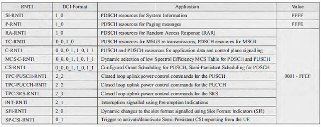
The set of RNTI is presented in below table . All RNTI have a length of  16 bits.

The Sl-RNTI is used to scramble the CRC bits belonging to DCI Format 1_0 when allocating PDSCH resources for the transmission of System Information. 3GPP has standardised a single SI-RNTI value which is used by all UE.

The P-RNTI is used to scramble the CRC bits belonging to DCI Format 1_0 when allocating PDSCH resources for the transmission of Paging messages, or when using the PDCCH to encapsulate a 'Short Message'. A 'Short Message' can be used to indicate that System Information content has changed and needs to be re-acquired. It can also be used to indicate an Earthquake and Tsunami Warnings.

System (ETWS) primary notification on SIB6, or an ETWS secondary notification on SIB9, or a Commercial Mobile Alert System(CMAS) notification on SIB8. 3GPP has standardised a single IP-RNTI value which is used by all UE.

RNTI as per 3GPP 38.321 Table 7.1-2


The RA-RNTI is used during the Random Access procedure when allocating PDSCH resources for the Random Access Response(MSG2). There is a one-to-one mapping between the RA-RNTI and the time-frequency resource used by the UE when transmitting the Random Access Preamble. This means that all UE using the same Random Access occasion will share the same RA-RNTI and the same PDCCH transmission. The content of the PDSCH differentiates between the set of UE using the Random Access Preamble Identity (RAPID) within the MAC sub-header.

The Temporary C-RNTl (TC-RNTI) is allocated during tbc Random Access procedure within the Random Access Response (MSG2).It is subsequently used to address the UE when allocating PUSCH resources for MSG3 re-transmissions. It is not necessary to use the TC-RNTI when allocating resources for the initial MSG3 transmission because that resource allocation is included within MSG2(rather than within a PDCCH transmission). The TC-RNTI is also used when allocating PDSCH resources for MSG4

The Cell RNTI (C-RNTI) is set equal to the TC-RNTI after successful Random Access contention resolution. The C-RNTI is changed whenever a UE completes a handover towards a new cell. The C-RNTI is used to address the UE when allocating PDSCH or PUSCH resources to that UE.


I-RNTI

The Inactive RNTI (1-RNTI) is applicable to the RRC Inactive State. In contrast to other RNTI, the I-RNTI is not used to scramble the CRC bits belonging to the PDCCH payload. instead, the 1-RNTI is used to address the UE within RRC signalling messages.

An I-RNTI can be allocated to a UE within an RRC Release message when moving the UE from RRC Connected to RRC Inactive.

There are two variants of the 1-RNTI:

  • A full I-RNTI which has a length of 40 bits. This variant can be included within an RRCResumeRequest1 message which has a size of 64 bits. This is relatively large for a MSG3 transmission, so there is a risk that uplink coverage may be compromised.
  • A short I-RNTI which has a length of 24 bits. This variant can be included within an RRCResumeReqest message which has a size of 48 bits. This is the normal size for MSG3 .

The useFullResumeID flag within SIB-1 instructs the UE to use either the full or short I-RNTI when resuming a connection, that means. this flag instructs the UE to send either an RRCResumeRequest message or an RRCResumeRequestl message.

The I-RNTI can be used to address a UE within an RRC Paging message when the UE is RRC Inactive state.

5G-NR: UE IDENTITIES

5G-NR: UE IDENTITIES

Introduction:
        The  UE identity is very important for authenticating the subscriber to access the network. authentication of subscriber is happened in various procedure  via RRC signalings. But to keep the subscriber safe, network allocated some unique identification, which  are used to identify the UE at various nodes. 

IMSI:

        The international Mobile Subscriber Identity (IMSI) is a globally unique permanent subscriber identity associated with in the USIM. An IMSI can be moved between UE by moving the USIM.

An IMSI is stored on the USIM and by the User Data Management (UDM) Network Function within the 5G Core Network.

The structure of an IMST is illustrated in below Figure.
  • The 'home' Public Land Mobile Network (PLMN) is identified using a combination of the Mobile Country Code (MCC) and Mobile Network Code (MNC). The ITU is responsible for allocating the MCC, whereas the national administrator is responsible for allocating the MNC. A UE uses the 'home' PLMN Identity when searching for a network, e.g. when completing a band scan, a UE will search for a cell which is broadcasting the 'home' PLMN Identity within SIB 1.
  • The subscriber is identified within the home PLMN using the Mobile Subscriber Identification Number (MSIN). 
  • MSIN is allocated by the service provider.


The IMSI can be used as the '5GS Mobile Identity' within NAS signalling procedures. 

For security reasons, the IMSI is included within NAS messages using a 'concealed' format which can hide the actual value. 

The 'Protection Scheme' indicated as part of the '5GS Mobile Identity' field can be set to 'null' in which case the IMSI is visible within the message.  

Some protection schemes are used to encrypt the IMSI prior to including within the message.

In the case of 5G, the IMSI is not used for paging procedures.


IMEI:

The International Mobile Equipment Identity (IMEI) is a permanent identity belonging to a device. 
It is stored within the device hardware and by the User Data Management (UDM) Network Function within the 5G Core Network.

The structure o1ran IMEI is illustrated in below figure.
  • The Type Allocation Code (TAC) is an 8 digit number which identifies the UE model. It can also identify a specific version of a UE model, i.e. different versions of the same UE model can be allocated different TAC. The TAC is allocated by the GSM Association (GSMA).
  • The Serial Number (SNR) uniquely identifies a device with a specific TAC. All UE which have the same TAC should be allocated different Serial Numbers. The Serial Number is allocated by the device manufacturer.
  • The Check Digit (CD) is calculated from a combination of the TAC and Serial Number. It provides a mechanism for detecting data entry errors, e.g. when the IMEI is manually entered into a system. 


The IMEI can be used within NAS signalling procedures as the '5GS Mobile Identity'. 

In contrast to the IMSI, the IMEI does not use a 'Protection Scheme' to provide encryption. Instead, the IMEI can be included directly within NAS signalling messages.


5G(NR): Scheduling Request


5G(NR): Scheduling Request:

This Blog will explain about the NR scheduling request mechanism which is applicable between UE and gNodeB. 

The Scheduling Request is triggered when UE is in uplink sync with gNodeB and It is not having and up-link (PUSCH/PUCCH) resource allocated for transmission of  new user plane or control plane data. 

 
The Scheduling Request (SR) is used for requesting UL-SCH resources( up-link grant ) for new transmission on PUCCH channel. 
 
Network (gNodeB) replies the UE with uplink grant in DCI 0_0 or DCI 0_1 messages on PDCCH channel.  


Configuration:
 
RRC connection setup or RRC reconfiguration request are used to configure the scheduling request related parameters. 
 
 
-MAC is controling the SR and the IE MAC-CellGroupConfig is used to configure MAC parameters for a cell group.
 

MAC-CellGroupConfig ::= SEQUENCE {  

      drx-Config SetupRelease { DRX-Config } OPTIONAL, -- Need M 

      schedulingRequestConfig

       bsr-Config

       tag-Config     

       phr-Config

       skipUplinkTxDynamic BOOLEAN,  

... }

-The IE SchedulingRequestConfig is used to configure the parameters, for the dedicated scheduling request (SR) resources. 


SchedulingRequestConfig ::= SEQUENCE {

    schedulingRequestToAddModList       SEQUENCE

                                               SchedulingRequestToAddMod  OPTIONA,

    schedulingRequestToReleaseList      SEQUENCE

                                               SchedulingRequestId  OPTIONAL -- Need N

}


SchedulingRequestToAddMod ::= SEQUENCE {

    schedulingRequestId                 SchedulingRequestId,

    sr-ProhibitTimer                    ENUMERATED {ms1, ms2, ms4, ms8, ms16,

                                                    ms32, ms64, ms128}

    sr-TransMax                         ENUMERATED {n4, n8, n16, n32, n64,

                                                    spare3, spare2, spare1}

}


- The IE "SchedulingRequestId" is used to identify a Scheduling Request instance in the MAC layer.


 SchedulingRequestId ::= INTEGER (0..7)


Each SR configuration corresponds to one or more logical channels. Each logical channel may be mapped to zero or one SR configuration, which is configured by RRC. 

 RRC configures the following parameters for the scheduling request procedure:  

- sr-ProhibitTimer (per SR configuration);  

- sr-TransMax (per SR configuration).


 SR will NOT be transmitted if:

  1. SR opportunity falls in measurement gap interval or
  2. another SR-Prohibit timer is running or
  3. DL PDCCH with UL resources is received.


5G(NR): MAC Control Elements

 MAC Control Elements:

- As we know that RRC and NAS messages functions are used to exchange the signalings between UE and gNodeB, But there are several communication path at MAC layer. so there are special MAC structures that carries special control information. These special MAC structure carrying the control information is called 'MAC CE', which means 'MAC Control Element'.
-
 -MAC CE works between UE(MAC) and gNodeB(MAC) for FAST Signaling Communication Exchange without  involving upper layers. 

- It is sent as a part of MAC PDUIt  always placed before any MAC SDUs LCID field denotes MAC CE Types.


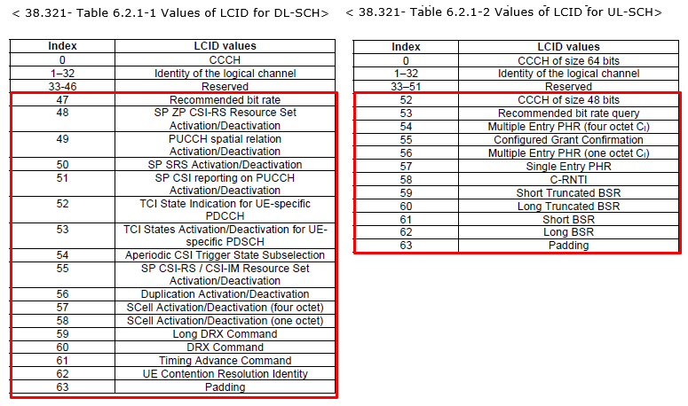
There are several Type of MAC-CE, MAC CE List specified in 38.321 v15.3:


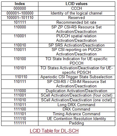
LCID VALUES FOR DL-SCH 

LCID Table for DL-SCH

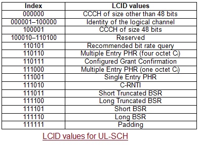
 LCID values for UL-SCH channel.

LCID Table for UL-SCH


MAC-CE and reference:


MAC CE

Reference

Buffer Status Report

38.321 - 6.1.3.1

C-RNTI

38.321 - 6.1.3.2

UE Contention Resolution Identity

38.321 - 6.1.3.3

Timing Advance Command

38.321 - 6.1.3.4

DRX Command

38.321 - 6.1.3.5

Long DRX Command

38.321 - 6.1.3.6

Configured Grant Confirmation

38.321 - 6.1.3.7

Single Entry PHR

38.321 - 6.1.3.8

Multiple Entry PHR

38.321 - 6.1.3.9

SCell Activation/Deactivation

38.321 - 6.1.3.10

Duplication Activation/Deactivation

38.321 - 6.1.3.11

SP CSI-RS / CSI-IM Resource Set Activation/Deactivation MAC CE

38.321 - 6.1.3.12

Aperiodic CSI Trigger State Subselection MAC CE

38.321 - 6.1.3.13

TCI States Activation/Deactivation for UE-specific PDSCH MAC CE

38.321 - 6.1.3.14

TCI State Indication for UE-specific PDCCH MAC CE

38.321 - 6.1.3.15

SP CSI reporting on PUCCH Activation/Deactivation MAC CE

38.321 - 6.1.3.16

SP SRS Activation/Deactivation MAC CE

38.321 - 6.1.3.17

PUCCH spatial relation Activation/Deactivation MAC CE

38.321 - 6.1.3.18

SP ZP CSI-RS Resource Set Activation/Deactivation MAC CE

38.321 - 6.1.3.19

Recommended bit rate MAC CE

38.321 - 6.1.3.20


MAC CE Header:


- below are the MAC Control Elements of Buffer Status Report:


1- Short BSR and Truncated BSR format :

2- Long BSR format: 


Format of C-RNTI MAC Control Element: 

C-RNTI MAC control element fields

UE Contention Resolution Identity MAC Control Element :

UE Contention Resolution Identity MAC control element IEs
- it has fixed 48-bit size
- UE Contentions Resolution Identity: This field contains uplink CCCH SDU.

3C : MAC subheader - Contention Resolution:
R = 0
R = 0
E = 1
LCID = 11100 = Contention Resolution.


Timing Advance Command MAC control element
1- Timing Advance Command is of 6 bits in length. TA (0, 1, 2… 63)
Power Headroom MAC Control Element : 


Power Headroom MAC control element
Activation/De-activation MAC Control Element : 
- The Ci field is set to '0' to indicate that the SCell with SCellIndex i shall be de-activated.


Activation/De-activation MAC control elements

Padding MAC Sub-Header:


1F : MAC subheader - Padding
R = 0
R = 0
E = 0
LCID = 11111 = Padding